If you’ve ever designed a PCB for automotive Ethernet, you already know how tricky it can get.
At first, everything seems fine—the board powers up, the link establishes, and packets start flowing.
But then problems show up.
Maybe the Ethernet drops randomly, maybe data gets corrupted, or maybe it only works at low speeds but fails when pushed harder.
It feels like something invisible is messing with your signals. And that invisible thing is poor signal integrity.
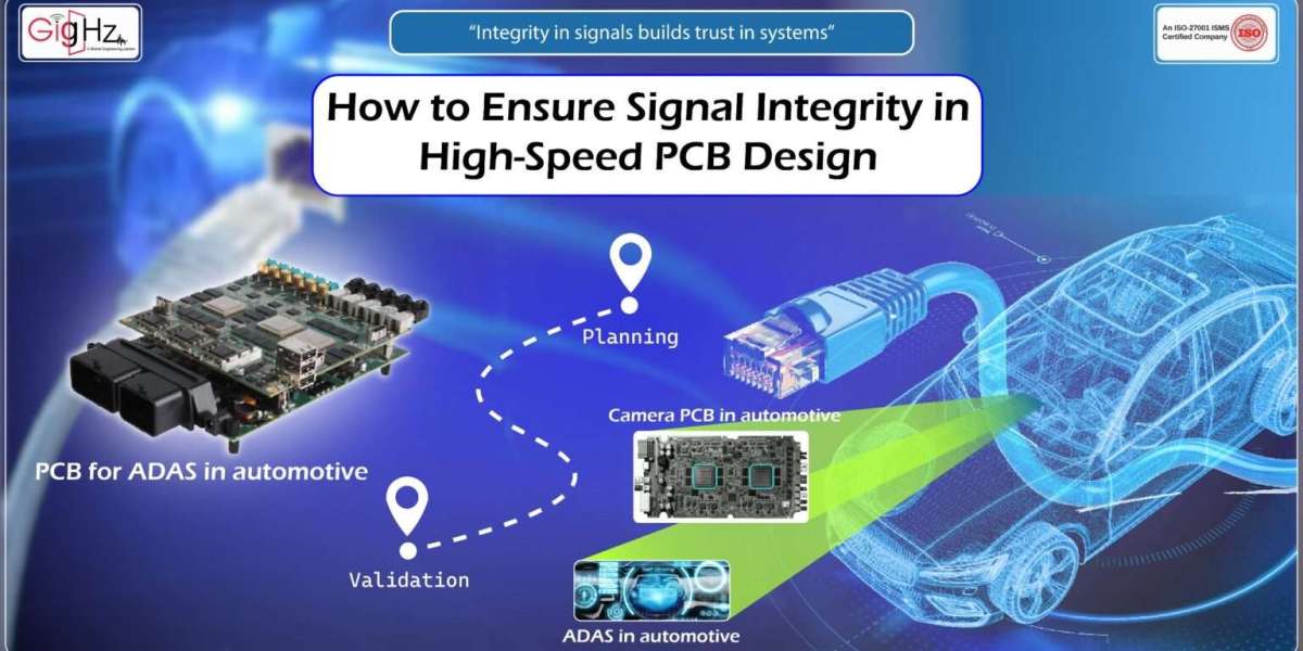
In signal integrity high-speed PCB design, especially for automotive Ethernet, signal integrity is not just a nice-to-have.
It’s the difference between smooth data transfer and hours of frustrating debug.
And in cars, where Ethernet connects safety-critical systems like ADAS and cameras, mistakes are simply not acceptable.
The good news is that signal integrity doesn’t depend on luck.
It comes from a clear process. Think of it in three phases: Planning → Execution → Validation.
Each phase connects to the next, and together they guide you from the first sketch to a reliable, road-ready board.
Phase 1 – Planning: Setting the Foundation
Most signal integrity problems begin long before routing starts. That’s why planning is the foundation—you’re shaping the conditions that make clean signals possible.
1. Decide the PCB Stack-Up Early
Your Ethernet differential pairs must stay around 100-ohm impedance from start to finish.
That depends on the PCB stack-up: the number of layers, the material thickness, and the copper weight.
If you delay this decision, you may end up with traces that can’t meet the requirement.
Working with your fabricator early ensures your calculations match what they can actually produce.
2. Plan for Clean Power
Even if your routing is perfect, Ethernet won’t work if the PHY chip gets noisy power.
That noise slips into the signals and ruins integrity.
During planning, decide where to place decoupling capacitors, how to arrange power planes, and how return currents will flow. Stable power gives you stable signals.
3. Identify the Critical Nets
Not all signals are equally important.
Some can live with a bit of delay or noise, but Ethernet cannot.
It carries the lifeblood of the vehicle network.
That means you should give Ethernet routes priority in your layout plan—set their paths before you worry about slower lines like LEDs or control signals.
Planning may feel like preparation, but it directly affects execution. If the foundation is right, the next phase becomes far easier.
Phase 2 – Execution: Turning the Plan into Layout
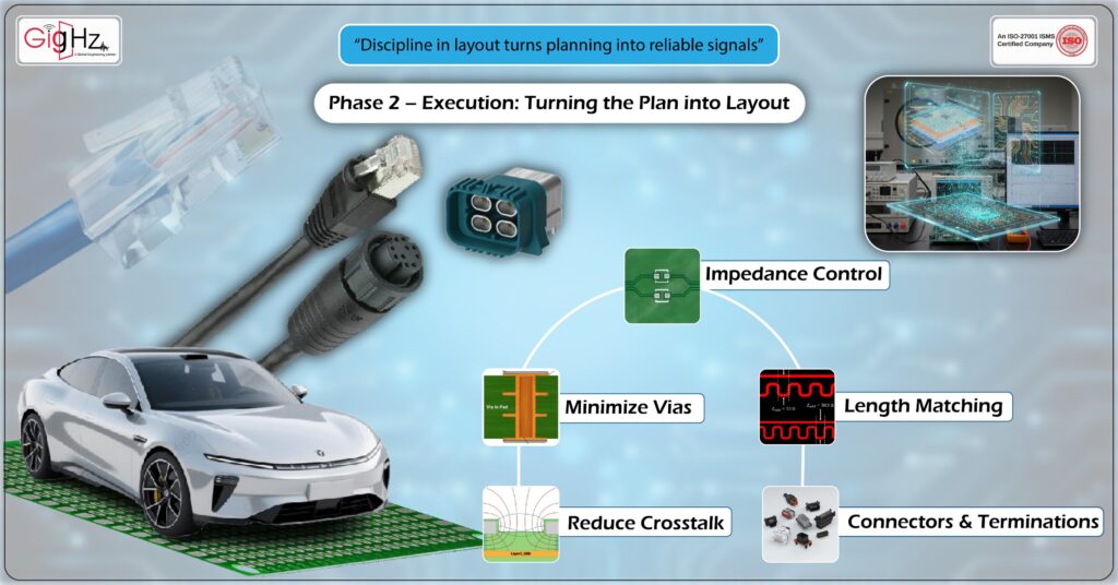
With the foundation in place, layout is where planning turns into real copper traces.
Every choice here either preserves or harms signal integrity.
1. Keep Impedance Controlled
This is where the 100-ohm target becomes reality.
Route differential pairs with the exact width and spacing your stack-up requires.
Even small deviations introduce reflections. Those reflections distort signals, create jitter, and lead to errors on the link.
2. Match the Pair Lengths
Differential pairs must arrive in sync. If one trace is longer, the pair becomes skewed, and the PHY may struggle to decode the data.
Keep the lengths equal. If you need to adjust, use smooth meanders instead of sharp zigzags.
3. Minimize Vias
Each via adds delay and distortion.
A few may be fine, but too many will harm the signal.
If a via is unavoidable, place a ground via nearby so the return current stays continuous.
4. Reduce Crosstalk
Cars are noisy by nature—motors, converters, ignition sparks.
If Ethernet traces run too close to other lines, interference will couple in.
Use the “3W rule”: keep at least three times the trace width as spacing.
If space is tight, ground shielding or careful layer choice helps reduce noise pickup.
5. Be Careful with Connectors and Terminations
Your signals don’t stop at the PCB. They travel through connectors and cables.
If these don’t maintain 100-ohm impedance, reflections appear at every interface.
Always select automotive-grade connectors and follow the PHY datasheet for resistor placement.
Execution connects directly to planning. All the early decisions on stack-up and power now show their value.
A well-planned design makes disciplined routing possible.
Phase 3 – Validation: Testing Before It’s Too Late
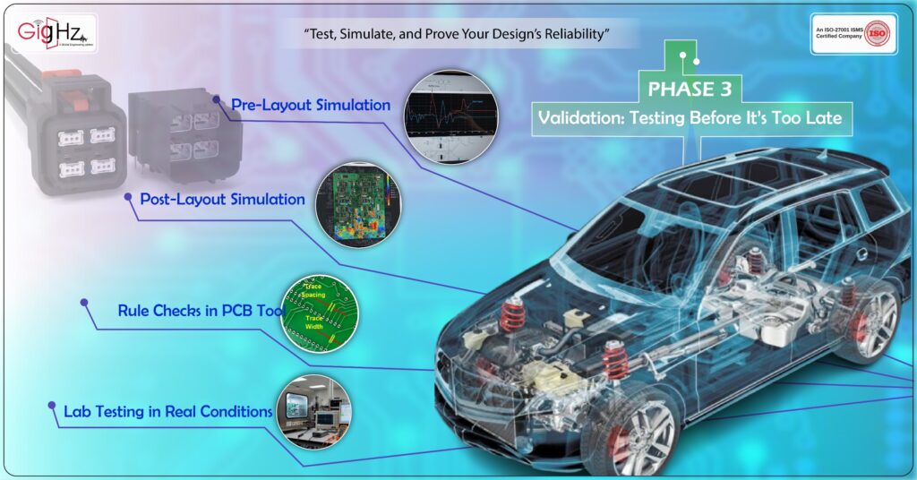
Even if your layout looks perfect, you can’t assume the signals will behave as expected. Validation is where you prove the design in both theory and practice.
- Pre-Layout Simulation
Before final routing, simulate the planned Ethernet paths.
This helps catch reflection or impedance issues while changes are still easy.
- Post-Layout Simulation
After routing, simulate again. Now you can see the effect of vias, spacing, and coupling.
For automotive Ethernet, check EMC performance too—the car environment is full of interference, and your design must handle it.
- Rule Checks in Your PCB Tool
Design tools let you set rules for width, spacing, and length matching.
Running these checks prevents small errors from slipping through unnoticed.
- Lab Testing in Real Conditions
Finally, test the real board. Use oscilloscopes and Ethernet testers to check eye diagrams, jitter, and error rates.
But don’t just test at room temperature—cars face heat, cold, and vibration. Testing under real-world stress ensures your Ethernet link will be reliable on the road.
Validation ties the process together. Planning sets the foundation, execution applies discipline, and validation confirms it all works.
Conclusion
Signal Integrity in High-Speed PCB Design isn’t about tricks. It’s about following a connected process:
- Plan the stack-up, power delivery, and routing priority.
- Execute with discipline—control impedance, match pairs, minimize vias, and reduce crosstalk.
- Validate through simulations and real-world tests before release.
Automotive Ethernet makes this even more important.
It is the nervous system of modern vehicles, carrying data between ECUs, sensors, and infotainment. If the signals stay clean, the whole system runs smoothly. If they fail, everything suffers.
So next time you sit down to design, don’t rush straight into routing.
Take a step back, follow the three phases, and give your Ethernet signals the care they deserve.
This content is originally posted on: https://gighz.net/
Source URL: https://gighz.net/analysis-simulation/signal-integrity-in-high-speed-pcb/