Electronics goods need to keep their cool for their proper functional and longevity.
Today, the requirement is compact devices with high processing capabilities, and the challenge of a PCB designer is to manage heat during charging and discharging.
As a CEO and PCB Designer, I can vouch that excessive heat is like diabetes for electronic components- A Silent Killer.
We don’t need catastrophic destruction at the final stage or performance issues reducing the product’s lifespan.
That’s why it’s important to incorporate effective PCB thermal management techniques well before the production phase to ensure optimal thermal performance.
In this blog, I will share my go-to effective heat dissipation strategies that can make your automotive tool cutting-edge. My years of experimentation, exhaustive discussions, and hit-and-trials have helped me create strategic approaches that enhance product performance under real-world conditions.
1. Strategic Component Placement
The arrangement of PCB components determines how heat will distribute throughout the system. Power transistors, regulators, and processors must be located in broader locations on a PCB board layout to avoid thermal interferences between the components.
Best practices include:
- Heat-producing components should be located next to board edges because strong air currents tend to exist in these areas.
- Hot components need enough distance between each other to avoid thermal clustering.
- The placement of fragile board components at locations away from large heat-producing areas.
- The direction of natural convection needs to be considered in PCB thermal design due to hot air rising upwards.
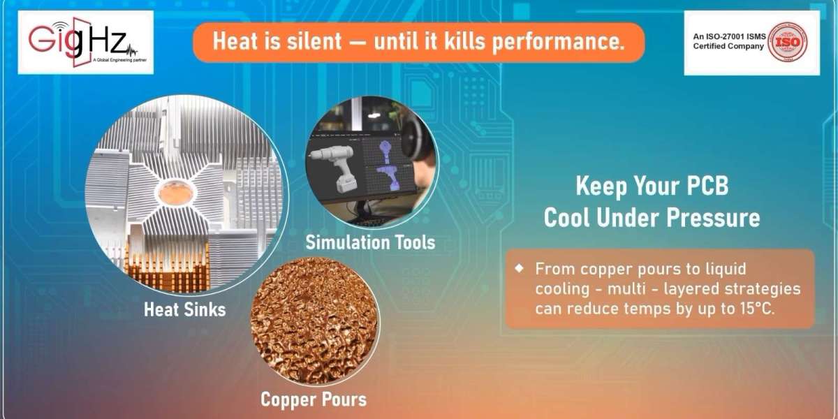
2. Copper Pour and Thermal Vias
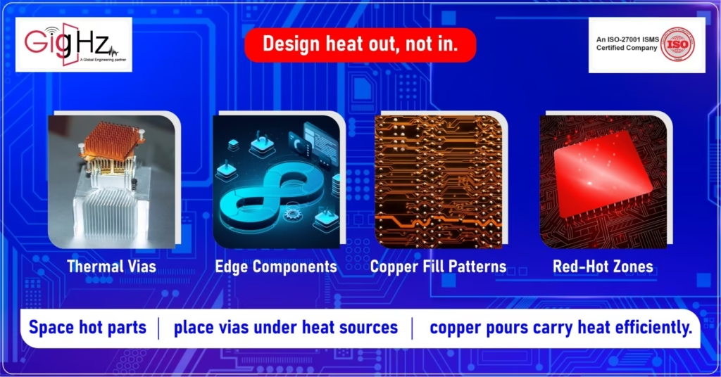
Do you know the thermal conductivity of copper exceeds FR-4 substrate material by 400 times? That’s why copper is highly recommended for heat dissipation. Placing ample amounts of copper on the board establishes effective heat distribution pathways that remove heat from components.
Furthermore, thermal vias establish vertical heat transfer channels that boost this effect across the entire board. The purpose of specialized vias is to bridge copper regions across multiple layers, so they form a three-dimensional thermal transport system.
For maximum effectiveness:
- Using larger diameter vias measuring 20-30 mils is ideal for thermal applications.
- Installing via arrays below hot components especially under hot areas.
- Linking thermal vias to internal ground planes and external copper pours.
- Using thermally conductive materials for filling thermal via cavities.
The strategic placement of copper and thermal vias during PCB thermal analysis demonstrates the ability to decrease hotspot temperatures by 10-15°C without producing excessive cost.
3. Multi-Layer Thermal Design
Most contemporary printed circuit boards now use multiple layers instead of two, which makes PCB thermal management more effective. Using internal layers for heat spreading enhances thermal performance significantly.
Key strategies include:
- Internal layers must be designated as thermal planes
- Ground planes should be designed without interruptions to fulfill both electrical and thermal requirements.
- For thermal layers, it’s ideal to use thick copper, approx 20z or more.
- The separation of thermal zones can be done using split thermal planes.
The board functions as an integral heat dissipation system in this thermal management approach thus decreasing dependency on the external cooling systems.
4. Heat Sink Integration
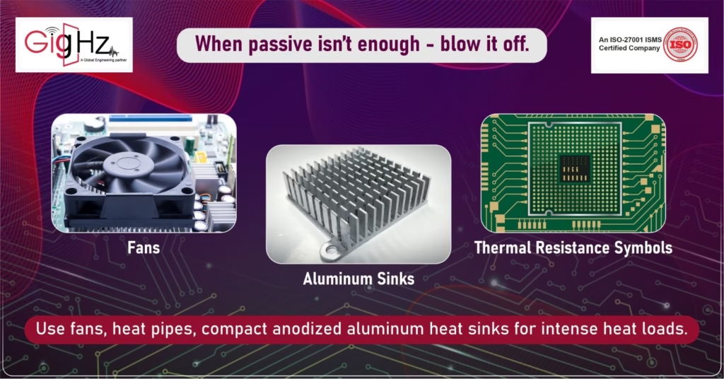
Over the years, I have found Heat Sink Integration is an effective solution for extending surface area, as it allows heat dissipation when basic PCB heat dissipation techniques prove to be insufficient. It is not merely attaching metal fins to hot components. It’s important to consider the dissipation of heat from a high temperature to a low temperature area as the amount should be directly proportional to the temperature difference.
Advanced approaches include:
- The engineer can incorporate heat sink mounting points into the PCB heat sink design.
- PCB designers should use thermally conductive adhesives or compounds to enhance component contact.
- The application of small and compact heat sinks designed for surface mount devices in limited space systems.
- Heat pipes are a perfect solution to redirect heat from its source to distant heat sinks.
A heat sink’s efficiency derives mainly from its thermal resistance measurements that depend on material selection, surface area, fin design, and surface treatment. The combination of performance quality, weight efficiency, and cost effectiveness makes anodized aluminum heat sinks suitable for most applications.
5. Thermal Interface Materials
The thermal resistance between components and heat sinks becomes significant due to the microscopic surface irregularities which form air gaps. The gaps between heat sink components get filled by thermal interface materials (TIMs) to achieve maximum thermal conductivity.
Modern TIM options include:
- The application of thermal greases and pastes allows easy implementation, but they tend to dry out with time.
- Phase-change materials turn solid at room temperature, but become liquid when the system operates.
- Thermal pads are convenient pre-cut solutions ensuring consistent performance.
- The use of graphite sheets provides excellent lateral heat spreading.
The selection of appropriate TIM depends on how well it conducts heat while maintaining electrical insulation, while offering simple application and extended reliability in the PCB thermal design.
6. Active Additional Air Cooling
The additional thermal capacity from forced air cooling is the only option when passive cooling techniques have exhausted their capability. The PCB surface will receive improved convection cooling by using fans or blowers in this method.
Effective implementation requires:
- Analysis of airflow patterns through computational fluid dynamics.
- The components need proper placement to optimize airflow movement based on their direction.
- It is important to consider air pressure zones and potential dead spots.
- The process of finding equilibrium between noise generation and cooling requirements.
The placement of components becomes more efficient when analyzed through PCB thermal analysis software, which results in improved heat dissipation performance.
7. Conformal Coatings with Thermal Properties
The main purpose of conformal coatings is environmental protection yet some specific formulations contribute to PCB thermal management. Thermally conductive conformal coatings spread heat evenly across the board surface.
Benefits include:
- Enhanced surface area for heat dissipation
- These coatings provide defense against environmental elements that would damage thermal performance.
- Heat spreading properties prevent hotspot formation because of better thermal distribution.
- Compatible with other thermal management and PCB heat dissipation techniques.
Specialized coatings in PCB thermal management have emerged as a new area that enhances traditional heat management methods.
8. Thermal Simulation and Analysis
Designers use simulation tools for complete PCB thermal analysis before manufacturing to detect hotspots and find optimal thermal solutions. The simulations analyze the heat production, heat movement, and heat removal processes across the board under varying operating circumstances.
Modern thermal simulation tools provide:
- Steady-state and transient thermal analysis
- Component-level temperature predictions
- Airflow modeling and optimization
- The evaluation of various cooling solutions operates through “What-if” scenario testing.
Through detailed thermal simulation companies can prevent expensive product redesigns and field failures because thermal problems can be detected in advance.
9. Power Management Techniques
The most effective thermal solution emerges from reducing heat production at its source. Intelligent power management systems create major reductions in heat load while simultaneously enhancing system energy efficiency.
Effective approaches include:
- Sleep-mode on: using this technique when components are inactive to enter the sleep state resulting in saving power.
- Scaling frequency: The system controls its operational frequency in response to changing processing requirements.
- Conducting voltage optimization to cut down power usage.
- Balancing load across different active components and systems.
The combination of these methods generates two important benefits, which include reduced thermal stress and longer battery life in portable systems.
10. Liquid Cooling Solutions
The combination of liquid cooling systems delivers maximum heat removal capacity in compact form for handling severe heat conditions. Initially, the liquid cooling solution was used in high- computing applications, but now they have are practical and viable option for specialized PCB thermal designs as well.
Modern implementations include:
- Closed-loop liquid cooling systems
- PCB assemblies with integrated cold plates.
- Dielectric fluid immersion for selected components.
- Microfluidic channels integration into the PCB layout design.
The implementation of liquid cooling systems requires higher complexity than air-based solutions, but delivers thermal performance beyond their capability making it ideal for high-power density applications.
Conclusion
Undoubtedly, a successful PCB thermal management system needs to be developed with a multi-faceted approach. Different techniques when applied together based on your specific application requirements will help build designs that preserve optimal operating temperatures under demanding conditions. Thermal planning needs to be incorporated during the initial design stages of your PCB project rather than just an afterthought. A complete thermal analysis process during development guarantees your products will maintain reliability and sustain throughout its expected lifespan.
This content is originally posted on: https://gighz.net/
Source URL: https://gighz.net/analysis-simulation/10-proven-pcb-thermal-management/